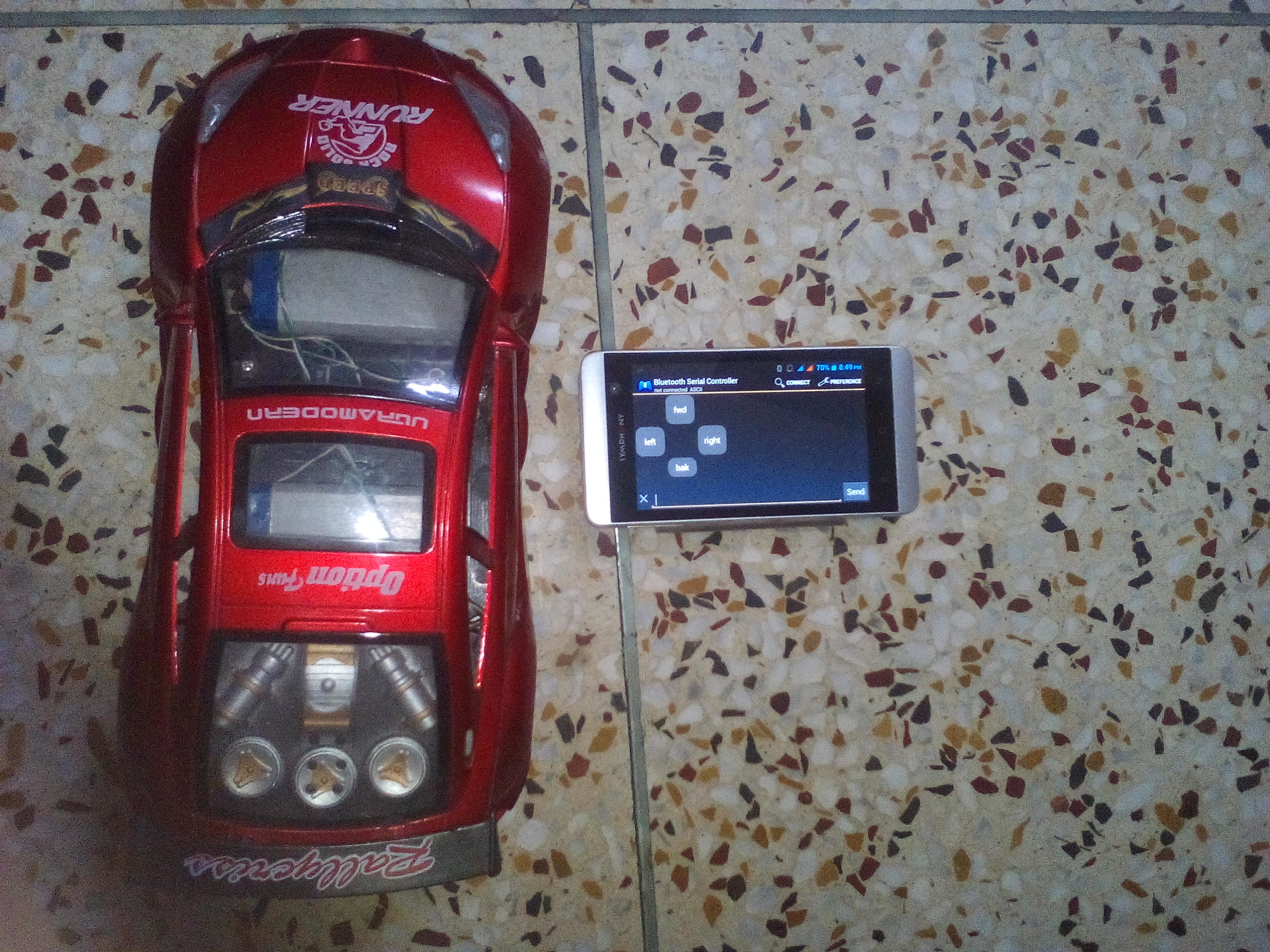
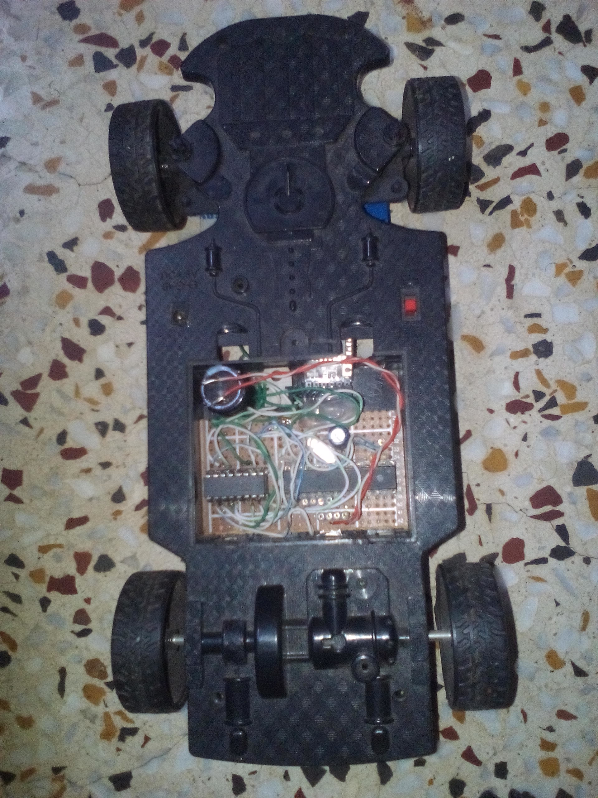
Its really fun to control a R/C car from a android phone.
However in my previous post i have discussed how to control a vehicle by bluetooth from laptop or android phone. That has a tank like mechanism and easier to implement the movements with on/off of the left side/right side motor(no simultaneous control). But when it comes to a normal car-like mechanism, the previous codes would not work.
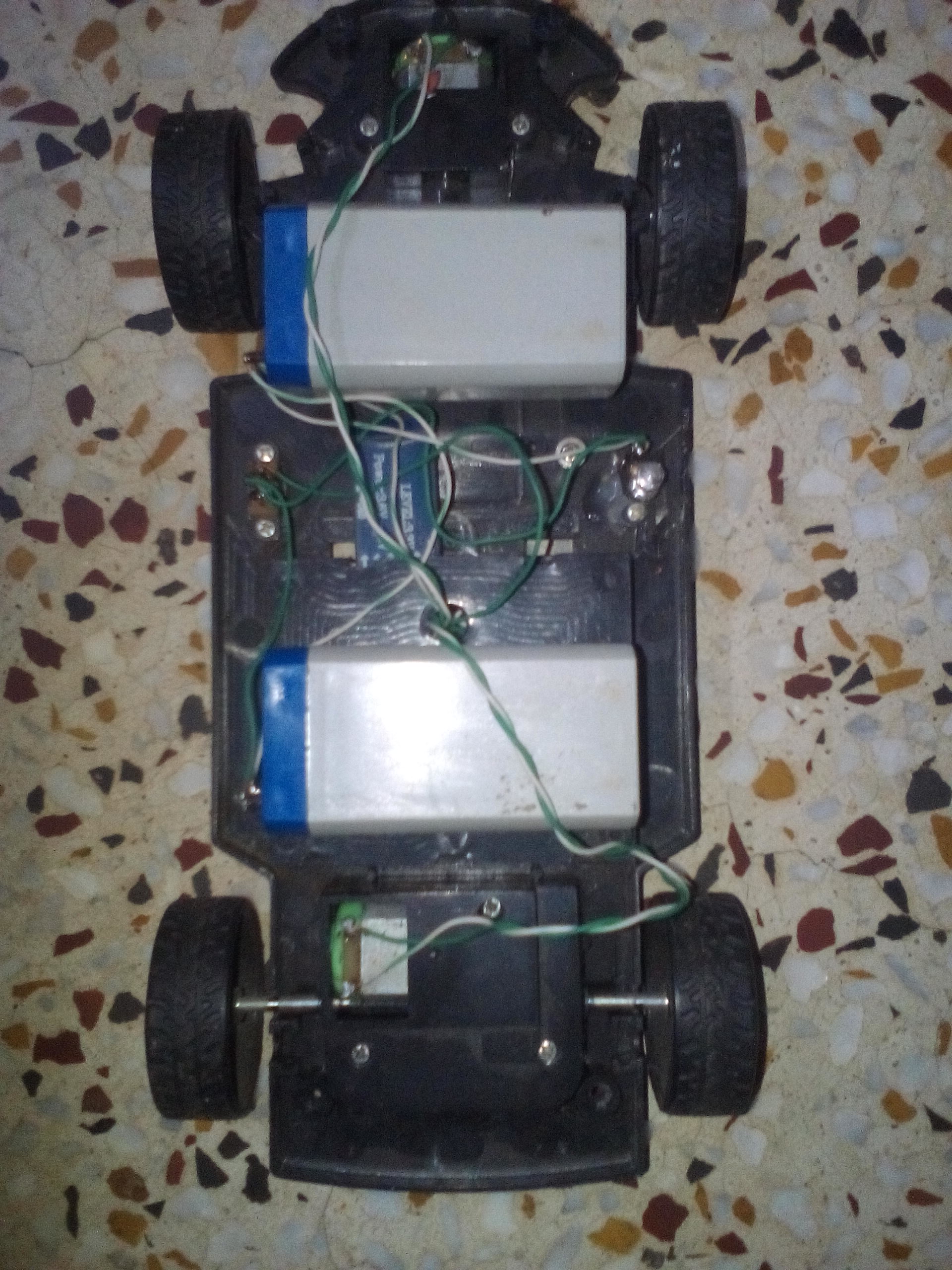
In a car like mechanism, we have to control the both motor simultaneously. The rear wheel motor controls the front and back movements and front motor tilts the front wheel. When taking a turn, both motors needs to be controlled.
And another feature is required. We have to detect the tapping/tap-and-hold on the screen controls to implement it.
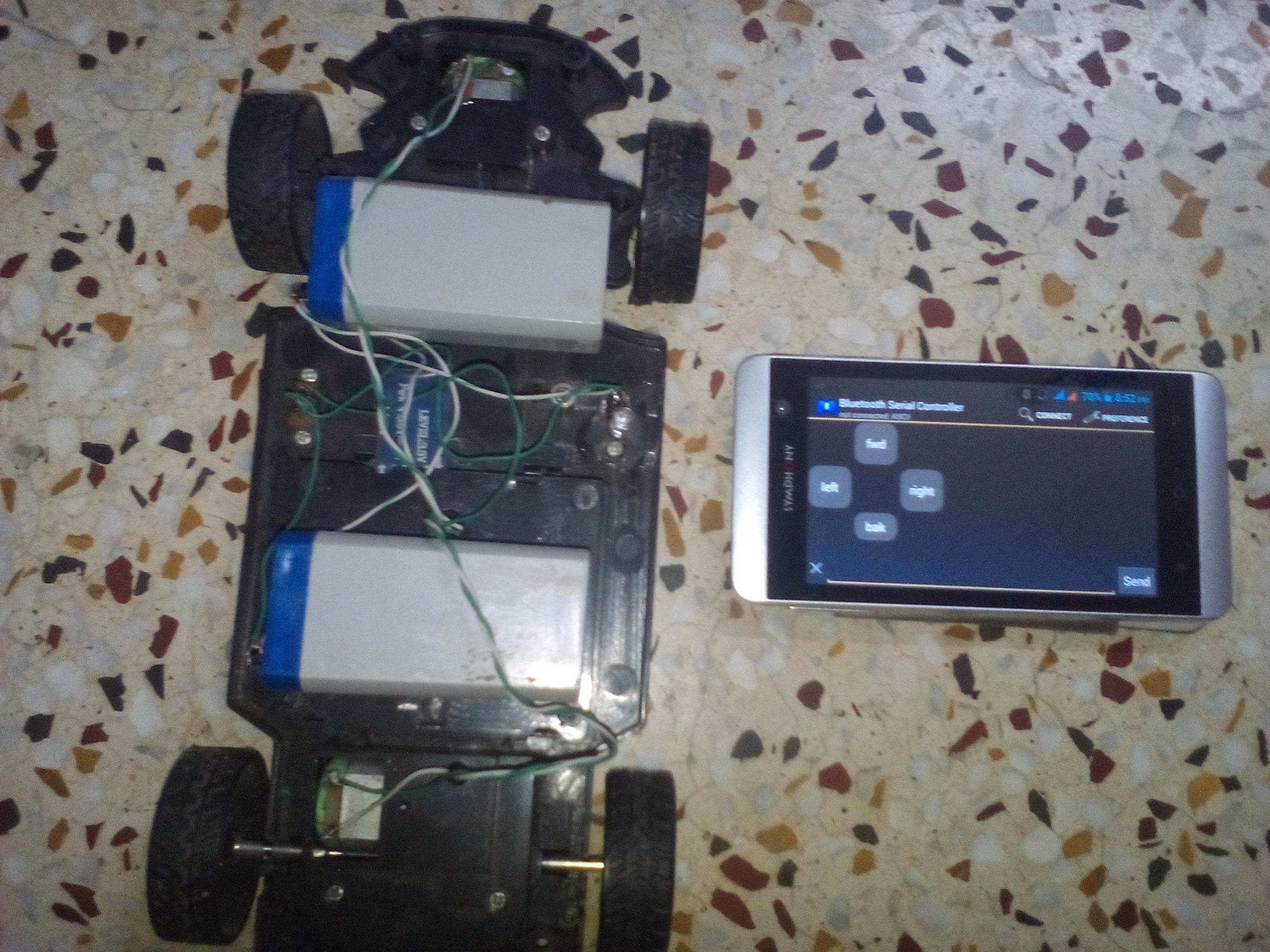
Since i am not a good android developer, i have to implement it in the arduino side. We will use the Bluetooth Serial controller app in the android phone. Bluetooth Serial Controller is customizable and fit our needs. It is pretty hard to design a tap, tap-and-hold, drag control and a protocol to communicate the car and phone.
So, in this case we will design a timing based control(cheating?). No, this is not cheating. this is somewhat another way to achieve the same result(it needs some value to be set for a specific car).
Ok, Enough, lets go to the main story.
Code and Explanation:
[code language=”cpp”]#define Forward 0
#define Backward 1
#define Left 2
#define Right 3
#define Break 4
#define True 1
#define False 0
char incomingByte;
int Command[5]={0,0,0,0,0};//forward, Backward, Left, Right, Off
int tTime=0, rTtime=0;
void setup() {
Serial.begin(9600);
pinMode(5,OUTPUT);
pinMode(6,OUTPUT);
pinMode(7,OUTPUT);
pinMode(8,OUTPUT);
pinMode(9,OUTPUT);
pinMode(10,OUTPUT);
pinMode(19,OUTPUT);
digitalWrite(5, LOW);
digitalWrite(6, LOW);
digitalWrite(7, LOW);
digitalWrite(8, LOW);
analogWrite(9,10);
analogWrite(10,10);
Command[Forward]==False;
Command[Backward]==False;
Command[Left]==False;
Command[Right]==False;
}
void loop() {
if (Serial.available() > 0) {
incomingByte = Serial.read();
if (incomingByte == ‘w’) {
tTime=0;
Command[Forward]=True;
Serial.write(‘g’);
}
else if (incomingByte == ‘s’) {
tTime=0;
Command[Backward]=True;
Serial.write(‘s’);
}
else if (incomingByte == ‘a’) {
tTime=0;
Command[Left]=True;
Serial.write(‘a’);
}
else if (incomingByte == ‘d’) {
tTime=0;
Command[Right]=True;
Serial.write(‘d’);
}
else if (incomingByte == ‘u’){
analogWrite(9,20);
analogWrite(10,20);
}
else if (incomingByte == ‘y’){
analogWrite(9,40);
analogWrite(10,40);
}
else if (incomingByte == ‘t’){
analogWrite(9,60);
analogWrite(10,60);
}
else if (incomingByte == ‘r’){
analogWrite(9,80);
analogWrite(10,80);
}
else if (incomingByte == ‘e’){
analogWrite(9,100);
analogWrite(10,100);
}
else if (incomingByte == ‘o’) {
Command[Break]=True;
tTime=0;
digitalWrite(5, LOW);
digitalWrite(6, LOW);
digitalWrite(7, LOW);
digitalWrite(8, LOW);
Serial.write(‘o’);
}//for nested if-else
}//for serial.available
if (Command[Forward]==True)
{
digitalWrite(5, LOW); //back motor that propels[]
digitalWrite(6, HIGH);//go forward
Command[Backward]==False;
}
if (Command[Backward]==True)
{
digitalWrite(5, HIGH); //back motor that propels
digitalWrite(6, LOW);//go backward
Command[Forward]==False;
}
if (Command[Right]==True)
{
digitalWrite(7, HIGH); //right turns
digitalWrite(8, LOW);
Command[Left]==False;
}
if (Command[Left]==True)
{
digitalWrite(7, LOW); //left turns
digitalWrite(8, HIGH);
Command[Right]==False;
}
if (tTime>800)
{
tTime=0;
Command[Forward]=0;
Command[Backward]=0;
Command[Left]=0;
Command[Right]=0;
Command[Break]=0;
digitalWrite(5, LOW);
digitalWrite(6, LOW);
digitalWrite(7, LOW);
digitalWrite(8, LOW);
}
else
{
tTime++;
//rTtime++;
if (rTtime>1000)
{
//Serial.print(‘Ready’);
//rTtime=0;
}
}
}
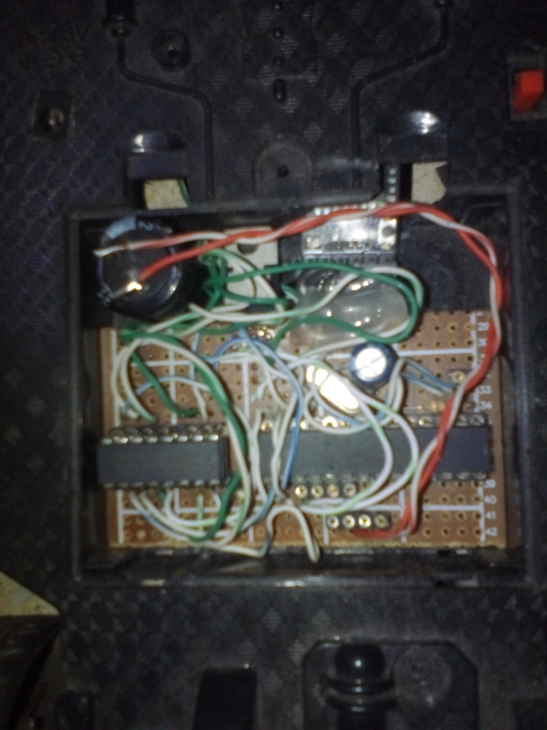
There is 2 pieces of 3.8V battery in series connection that makes a total of 7.6V. This voltage is directly fed to the L293D H-bridge. There are a 7805 voltage regulator used to regulate and reduce the 7.6V to 5V. That is fed to the microcontroller and h-bridge.
As like the previous circuit diagram, A L293D H-Bridge chip is used here. Pin 5, 6, 7, 8 of the arduino goes to input1(pin2), input2(pin9), input3(pin10), input4(pin15). Output4 and output3 of l293d goes to front steering motor. Output1 and output2 of l293d goes to rear wheel motor. Arduino pin 9 goes to enable1(pin1)of l293d and arduino pin 10 goes to enable2(pin9) of l293d. All other connections remains same like the previous circuit.
The TxD of bluetooth module goes to RxD of the atmega8 and the RxD pin of bluetooth module goes to TxD of atmega8.
The code was written in somewhat unnecessary complex-way. I have defined forward, backward left and right as a constant to represent the index of the Command[] array. When Command[Left] is used, it represents the Command[2], that is the 3rd element of the Command[] array.
Each elements of the array controls movement/direction of the front and rear motor.
There are a variable tTime. When any character is received from the serial port(tapping on the button > android sends character over bluetooth > the bluetooth module received the character and sent to the arduino > character is received inn the arduino over serial port.) reset the variable tTime to zero, otherwise increment it by 1. When tTime reaches over 800, reset all elements of Command[] array. That stops the car.

